How 2D drawings turn into parametric 3D models: the rebuild process, DWG/STEP/IGES file formats, and the QA checks that catch bad conversions.
What "2D to 3D CAD conversion" actually means
A 2D-to-3D conversion takes a drawing — a DWG, a PDF, or a scanned print with no digital file at all — and rebuilds it as a 3D CAD model with real feature history: extrudes, revolves, fillets, patterns, the tree a designer would build modeling the part from scratch. That's different from tracing a drawing's outline into a 3D shape. A traced model can look right in a screenshot and still be useless downstream: no parametric history means you can't change a hole diameter or add a fillet without rebuilding the geometry around it. The real test: can you edit one dimension and have the model update, the way you could on a part modeled natively?
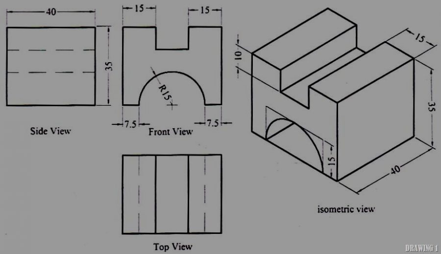
This matters most in three cases: the native CAD file is gone or unreadable, the part was only ever documented on paper, or a supplier drawing needs to become an editable model before anyone can quote tooling or run FEA against it.
The process
A conversion that produces an editable, trustworthy model runs through five steps:
- Intake and format triage. Source files get sorted by rework needed: vector DWG/DXF needs the least interpretation; PDFs are usually workable; scanned raster images (TIFF, JPG, a phone photo) need scale and skew corrected first, or every downstream dimension inherits the error.
- Rebuild as a parametric solid. The part gets modeled feature-by-feature in the target CAD system — not traced as a static shell. Each dimension on the source drawing becomes a driving dimension in the model, not just a number sitting next to a line.
- Reconstruct GD&T and tolerances. Datums, feature control frames, and tolerance callouts from the source drawing carry into the model and get checked against the part's actual geometry, not just copied over as text.
- Regenerate the 2D drawing from the model. The output drawing is associative — driven by the 3D model — so a later dimension change updates the drawing automatically instead of requiring a manual redraw.
- Deliver native and neutral files. The client gets the native CAD file, a neutral format for handoff, and the regenerated drawing, checked against the original before it ships.
File formats: what goes in, what comes out
Input quality drives everything downstream. DWG and DXF are vector formats — the geometry is already digital, so conversion is mostly interpretation, not reconstruction. PDFs work if the vector layer survived export from the original CAD system. Scanned raster prints (TIFF, JPG, a print photo) are hardest: line weight, scale, and skew all need resolving by eye before modeling starts, and a bad scale reference is the most common way a conversion ships wrong.
On the output side, the choice is between native and neutral formats, and it depends on what happens next:
- Native CAD file — the actual part file in the target platform. Use this if the model will keep getting edited in that system.
- STEP (AP203, AP214, or AP242) — the standard neutral handoff format. AP242 is the edition that can carry semantic PMI, meaning GD&T data travels with the geometry instead of getting lost in translation.
- IGES — an older neutral format some legacy systems still require. Less reliable than STEP at preserving solid geometry and GD&T, so it's a fallback, not a first choice.
- STL — fine for 3D printing or a visual check, not a source format for manufacturing, because it's a faceted mesh with no exact geometry or tolerance data.
The decision rule is simple: hand off STEP when the model needs to go to a shop or software the source system doesn't control. That's where independence becomes concrete, not just a tagline — CADmore doesn't manufacture, so a conversion deliverable is built to move. A STEP file with intact PMI can go to whichever shop ends up running the job, whether that's the customer's own manufacturer or a shop from CADmore's partner network, without anyone re-modeling the part first.
QA: how you know the model is actually right
QA is where most conversion failures show up, and it's the step that's easiest to skip under a deadline. A real QA pass checks:
- Dimension-by-dimension verification against the source drawing — every callout confirmed against the model, not a visual spot check.
- GD&T carryover — datums and feature control frames present in the model itself, not just noted on the drawing.
- Associativity — does the 2D drawing actually regenerate from the model, or was it redrawn separately and will drift the next time someone edits the part?
- Solid vs. surface integrity — a manufacturing-ready model needs to be a closed, watertight solid; stitched surfaces with a hairline gap will pass a glance and fail in CAM or FEA.
- Scale and unit sanity — inch/millimeter mismatches and scan-induced scale errors are common enough to check explicitly, not assume away.
Those five checks map directly to how conversions go wrong: geometry with no feature history, GD&T dropped in translation, a model and drawing that quietly diverge, a surface body masquerading as a solid, a scan whose scale reference was off by a few percent. A conversion that clears all five is one you can build on; skip even one and it usually looks fine until someone tries to change a dimension or send it to a machine shop.
What drives the cost
Sheet count, source quality, how much GD&T has to be reconstructed from scratch, and surfacing complexity (a simple prismatic bracket versus a freeform housing) are the main cost drivers on a conversion project. Pricing is typically structured per-sheet or hourly rather than as a flat fee. Most 2D-to-3D conversions run $150–$300.
Where CADmore fits
CADmore converts drawings as a design service — it isn't a manufacturer and doesn't run production. Prototypes get built in-house to validate a design, but the manufacturing itself goes through the customer's own manufacturer or CADmore's partner network, which is why the format choices above matter: a neutral handoff doesn't lock the customer into anyone's preferred shop. General design turnaround is as fast as 24 hours for simple jobs and typically 6-8 business days for standard scope, though a large legacy drawing set will run longer. CADmore has taken in tens of thousands of project submissions.
If you're not sure whether a drawing set needs a full rebuild or just cleanup, a $100 consultation can scope it before you commit to either.
Frequently asked questions
What's the difference between 2D-to-3D CAD conversion and reverse engineering?
Conversion starts from an existing drawing or legacy file — a DWG, DXF, PDF, or even a paper print — and rebuilds it as a parametric 3D model. Reverse engineering starts from a physical part with no usable drawing, typically using 3D scanning, and works backward to a CAD model. If a drawing exists but the file behind it is gone, that's conversion; if only the part exists, that's reverse engineering (CADmore's short-range 3D scanning starts at $260, with turnaround typically 8-10 business days).
What file format should I send for a conversion?
Vector formats — DWG or DXF — convert cleanest, since the geometry and text are already digital. PDFs work if the vector layer survived export. Scanned raster images (TIFF, JPG, a photo of a print) are usable but take longer, because scale, skew, and line-weight ambiguity all have to be resolved by hand before modeling starts.
What do I actually get back from a conversion — just a 3D model?
A complete conversion delivers three things: the native CAD file in the target platform, a neutral file (typically STEP) for handoff to any shop or software, and a regenerated 2D drawing that's associative to the model, meaning it updates automatically instead of being redrawn by hand.
Will the converted model include GD&T and tolerances?
It should. Datums, feature control frames, and tolerance callouts from the source drawing need to carry into the model and the regenerated drawing as part of the QA pass, not as an optional add-on. If GD&T is dropped or approximated, the conversion isn't done.
How long does a 2D-to-3D conversion take?
It depends on sheet count, drawing complexity, and source quality — a large legacy drawing set takes longer than a single clean DXF. CADmore's general design turnaround is as fast as 24 hours for simple jobs and typically 6-8 business days for standard scope.